LTE PUCCH-Physical Uplink Control Channel
LTE PUCCH-Physical Uplink Control Channel
LTE PUCCH channel or Physical Uplink Control Channel with respect to LTE system.
This LTE channel is used to carry UCI(Uplink Control Information). UCI can also be transported using PUSCH channel. An LTE UE can never transmits both PUCCH and PUSCH during the same subframe.
• If UE has application data OR RRC signalling then UCI is carried over PUSCH
• If UE does not have any application data OR RRC signalling then UCI is carried over PUCCH
This is a stand-alone uplink physical channel. This PUCCH control signaling channel comprises following:
• HARQ ACK/NACK
• CQI-channel quality indicators
• MIMO feedback - RI(Rank Indicator),PMI(Precoding Matrix Indicator)
• scheduling requests for uplink transmission
• BPSK or QPSK used for PUCCH modulation
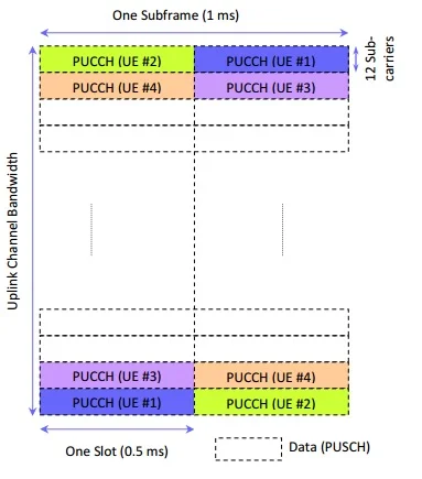
PUCCH consists of 1 RB/transmission at one end of the system bandwidth which is followed by another RB in the following slot(at opposite end of the channel spectrum). This makes use of frequency diversity with 2dB estimated gain. A PUCCH Control Region comprises every two such RBs.
| System BW In MHz | 1.25 | 2.5 | 5 | 10 | 15 | 20 |
|---|---|---|---|---|---|---|
| PUSCCH Control region | 1 | 2 | 4 | 8 | 12 | 16 |
| No.of resource blocks | 2 | 4 | 8 | 16 | 24 | 32 |
The standard specifies 6 LTE PUCCH formats as mentioned in the table-2 below. As mentioned PUCCH format 2a and 2b are not applicable for extended CP.
| LTE PUCCH Format | Modulation Index | No. Of Bits Per Subframe | No. Of REs Occupied(Normal CP) | No. Of REs Occupied(Extended CP) |
|---|---|---|---|---|
| 1 | - | - | 48+48=96 OR 48+36=84 | |
| 1a | BPSK | 1 | 48+48=96 OR 48+36=84 | |
| 1b | QPSK | 2 | 48+48=96 OR 48+36=84 | |
| 2 | QPSK | 20 | 120 | |
| 2a | QPSK+BPSK | 21 | 120 | Not Applicable |
| 2b | QPSK+QPSK | 22 | 120 | Not Applicable |
Table-2 LTE PUCCH Formats
| LTE PUCCH Format | No. Of Bits Per Subframe | Normal CP | Extended CP |
|---|---|---|---|
| 1 | - | Scheduling Request | |
| 1a | 1 | 1 x HARQ-ACK OR 1 x HARQ-ACK +SR | |
| 1b | 2 | 2 x HARQ-ACK OR 2 x HARQ-ACK +SR | |
| 2 | 20 | CQI | CQI OR HARQ-ACK+CQI |
| 2a | 21 | 1 x HARQ-ACK + CQI | - |
| 2b | 22 | 2 x HARQ-ACK + CQI | - |
Table-3 Information carried by each PUCCH format
The LTE PUCCH channel is allocated 2 RBs at the edges of channel BW. Each PUCCH transmission occupy 1 RB on each side of the channel bandwidth. These two RBs are distributed across two time slots. RB numbering for PUCCH starts on outside edges and increases inwards.
PUCCH is allocated RBs at the edge of channel BW to avoid fragmenting RBs available to PUSCH.
LTE PUCCH Channel Reference: 3GPP TS 36.211


Comments
Post a Comment