5G NR Network Interfaces-Xn,NG,E1,F1,F2 Interface Types In 5G
5G NR Network Interfaces-Xn,NG,E1,F1,F2 Interface Types In 5G
5G NR overall architecture is shown in the following figure-2. This is as defined in the 3GPP TS 38.300 specification. The 5G NR network composed of NG RAN (Next Generation Radio Access Network) and 5GC (5G Core Network). As shown, NG-RAN composed of gNBs (i.e. 5G Base stations) and ng-eNBs (i.e. LTE base stations).
• Xn interface exists between these base stations viz. between gNB-gNB, between (gNB)-(ng-eNB) and between (ng-eNB)-(ng-eNB). Xn is the network interface between NG-RAN nodes. Xn-U stands for Xn User Plane interface and Xn-C stands for Xn Control Plane interface.
• NG interface exists between 5GC and these base stations (i.e. gNB & ng-eNB).

Following are the interfaces and nodes as shown in the figure-1 and figure-2.
• NG-C: control plane interface between NG-RAN and 5GC.
• NG-U: user plane interface between NG-RAN and 5GC.
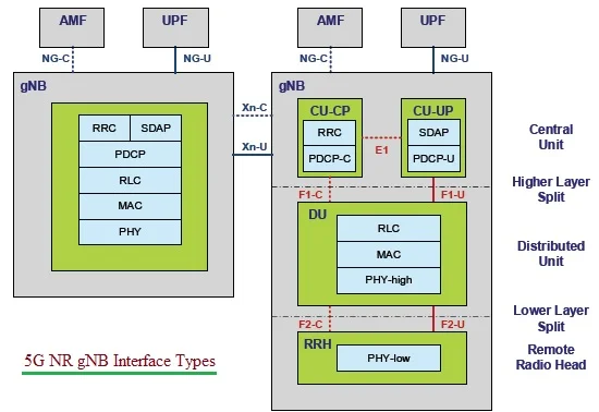
• gNB: node providing NR user plane and control plane protocol terminations towards the UE, and connected via the NG interface to the 5GC. The 5G NR (New Radio) gNB is connected to AMF (Access and Mobility Management Function) and UPF (User Plane Function) in 5GC (5G Core Network). The protocol layers are mapped into three units viz. RRH (Remote Radio Head), DU (Distributed Unit) and CU (Central Unit) as shown in the figure-2.
• ng-eNB: node providing E-UTRA user plane and control plane protocol terminations towards the UE and connected via the NG interface to the 5GC.
As shown in the figure-2, there are control plane and user plane interfaces towards the 5G Core network (5GC). Following are the locations and functions of 5G NR interfaces.
5G NR Xn Interface
• Location: Xn interface lies between NG-RAN Nodes viz. gNB & ng-eNB.
• Control Plane Functions are as follows:
-interface management and error handling (e.g. setup, reset, removal, configuration update)
-connected mode mobility management (handover procedures, sequence number status transfer, UE context retrieval)
-support of RAN paging
-dual connectivity functions (secondary node addition, reconfiguration, modification, release, etc.)
• User Plane Functions are as follows:
-Data Forwarding
-Flow Control
• References: TS 38.420 to TS 38.424
5G NR NG Interface
• Location: Between 5G RAN and 5G Core Network. Both control plane and user plane lies between them and hence there are two interfaces under NG interface viz. NG-C and NG-U. It is similar to LTE interfaces viz. S1-C and S1-U respectively.
• Functions/Objectives:
-NG interface supports the exchange of signalling information between NG-RAN and 5GC.
-It defines inter connection of NG-RAN nodes with AMFs supplied by different manufacturers.
-It specifies the separation of NG interface Radio Network functionality and Transport Network functionality to facilitate introduction of future technology.
• Capabilities:
-procedures to establish, maintain and release NG-RAN part of PDU sessions
-procedures to perform intra-RAT handover and inter-RAT handover
-the separation of each UE on the protocol level for user specific signalling management
-the transfer of NAS signalling messages between UE and AMF
-mechanisms for resource reservation for packet data streams
• References: From TS 38.410 to TS 38.414
5G NR E1 Interface
• Location: From logical perspective, E1 interface is point-to-point interface between a gNB-CU-CP and a gNB-CU-UP as shown in fig-2.
• Functions:
-E1 interface supports the exchange of signalling information between the endpoints.
-It separates Radio Network Layer and Transport Network Layer.
-It enables exchange of UE associated information and non-UE associated information.
• References: From TS 38.460 to TS 38.463
5G NR F1 Interface
• Location: Between gNB-CU and gNB-DU. It is also separated into F1-C and F1-U based on control plane and user plane functionalities.
• Functions:
-F1 interface defines inter-connection of a gNB-CU and a gNB-DU supplied by different manufacturers.
-It supports control plane and user plane separation.
-It separates Radio Network Layer and Transport Network Layer.
-F1 interface enables exchange of UE associated information and non-UE associated information.
• References: From TS 38.470 to TS 38.475
5G NR F2 Interface
This interface lies between lower and upper parts of the 5G NR physical layer. It is also separated into F2-C and F2-U based on control plane and user plane functionalities.


Comments
Post a Comment